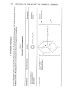
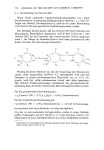
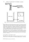
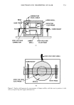
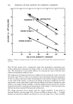
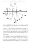
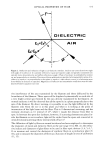
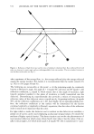
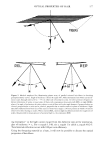
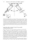
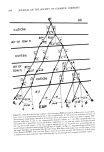
574 JOURNAL OF THE SOCIETY OF COSMETIC CHEMISTS OBLIQUE INCIDENCE If the same narrow beam of monochromatic light from a laser is incident obliquely on the filament, say at 20 or 60 ø as depicted in Fig. 1, and ifa hollow cylinder with an inner white-wall surface is placed coaxially with the filament, a circular band of diffracted spots will be seen on the wall of the cylinder. Again, by placing a white screen at various distances downstream from the point of intersection it can be shown that these spots appear only on the surface of a cone whose half-angle is (90-0i) where 0i is the angle of incidence (here shown as 20 or 60ø). In making a direct visual examination of the diffracted light, it is found that it can be seen easily only when the eye is on the sur- face of the proper cone and is looking at the point of intersection of the beam with the filament. This also is 2-dimensional scattering (confined to a surface), and its intensity falls off as 1/r. If the cross-section of the filament is not a circle, the cross-section of the cone will be altered likewise. If we have a number of filaments parallel to one another and illuminated similarly, each filament will produce its cone and the sum of the light from all the cones will determine the resultant cone whose surface will now have a finite thickness. REFLECTION OF LIGHT BY DIELECTRICS Before discussing the reflection and scattering of light by hair fibers, it appears desir- able to review certain fundamental laws which govern the reflection of light by dielec- tric materials. In Fig. 2 is depicted a ray of light incident at the angle •b on an air-dielec- tric interface. If the surface is optically polished, the scattering is negligible, and the ray is partly reflected at an angle •b and partly transmitted after refraction at an angle r. The angle of refraction is found from Snell's law sin r -- (sin •b)/n (1) where n is the refractive index of the dielectric. Calculating the reflection and trans- mission coefficients is somewhat more lengthy, involves the use of Fresnel's equations, and requires a knowledge of the direction of polarization of the incident light generally taken to be linearly polarized with the electric vector • vibrating parallel (%) or perpen- dicular (•s) to the plane of incidence which is defined by the incident ray and the per- pendicular to the interface. (In Fig. 2, the plane of incidence would be the plane of the paper.) Fresnel's equations enable us to calculate the amplitudes of the reflected (Rs, Ro) and transmitted (Ts, To) rays relative to the incident (Es, Eo) amplitudes and have the form -sin (O-r) tan (0-r) Rs/Es = and Rp/Ep = (2) sin (O+r) tan (O+r) 2 sin r cos 0 2 sin r cos 0 Ts/Es = and Tp/Eo = (3) sin (0 + r) sin (0 + r) cos (0 - r) To obtain the intensities of the reflected rays relative to those of the incident rays, the amplitudes are squared the reflection coefficients are given by rs = (Rs/Es) = and ro = (Rp/Eo) 2 (4)

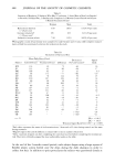
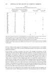
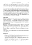
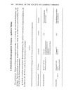
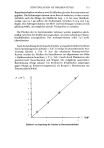
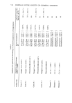
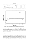
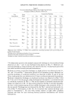
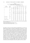
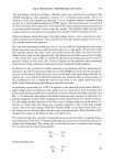
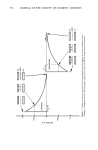
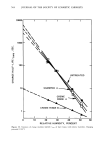
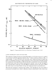
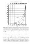
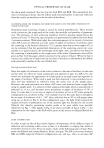
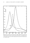
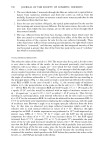
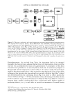
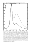
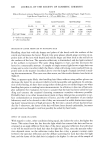
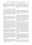
OPTICAL PROPERTIES OF HAIR 575 o.•1 0.8 0.'7 o.• 0.5 0.4 o.• 0.2 0.1 0" I0 ø 20 ø 3,0 ø 4• 50" 60" 70 ø 80' 90 ø Figure 3. Reflection coefficients (r) vs. angle of incidence (0) at air-dielectric (or dielectric-air) interface for dielectric having n = 1.548, value of np for exocuticle of human hair. Upper curve is for es. Lower curve for %, and intermediate curve for natural (unpolarized) light. Angle values at bottom apply to ray approaching interface from air those at top are angles of refraction which correspond to values of 0 at bottom. Angle 0B (equals tan -• n) is Brewster's angle of incidence for which rays polarized % suffer no reflection but are entirely transmitted. For ray inside dielectric trying to get out, Brewster's angle would be 32.86 ø for n = 1.548 The reflection coefficients for natural (unpolarized) light will be (rs + r•,)/2. When 4) equals 0 ø (normal incidence), we have rs = r•, = ru = (n - 1)2/(n + 1) 2 = 0.040 for n = 1.50 (5) Letting n = 1.548, assigning various values to 4) and calculating the corresponding values of r from Snell's law, Fresnel's equations are then used to derive the reflection curves shown in Fig. 3. Calculation of the reflection coefficients is straightforward, but calculating the value of a transmission coefficient at an interface for angles of incidence other than 0 ø is slightly more complicated because the relative areas of the beams on each side of the interface enter into the calculation. This arises since it is necessary to
Purchased for the exclusive use of nofirst nolast (unknown)
From: SCC Media Library & Resource Center (library.scconline.org)