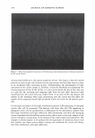
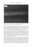
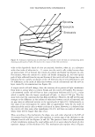
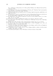
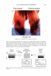
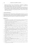
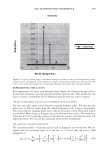
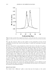
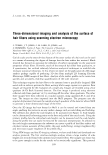
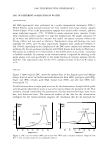
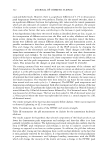
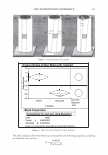
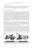
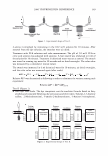
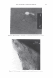
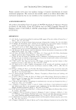
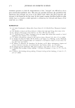
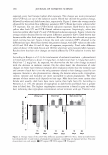
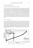
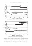
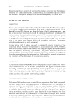
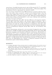
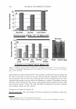
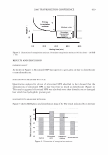
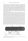
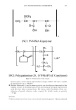
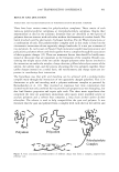
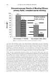
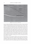
296 JOURNAL OF COSMETIC SCIENCE \ \ Tip to Root \ \ I I I I Figure 1. A depiction of the surface of a hair, showing: the rake angle"{. The normal the cuticle is shown as a dashed line. The "expected reflection direction" is shown in blue. The outgoing direction of the outgoing beam is deviated by 2"{ in each case, as shown above. The effective period is the revealed face of the cuticle, and the depth of the grating is simply the thickness of a cuticle. The condition is that: More generally we have, P sin 0 = mA.. ml\ mK Li�= Sin0incidenc - Sin0diffracted = p = T· (la) (lb) The integer, m, specifies the diffraction order (0, ±1, ±2, ±3, etc.). The wavelength of the light is A., while k = 2Tr!A. is the associated wavevector. The grating period is denoted with P, while K = 2TrlP is defined as the grating wavevector. We can find an expression for the optical electrical field by noting how the grating affects the incoming wave. First there is a reflection coefficient, r. This multiples the overall amplitude. There is also a reversal in direction in the y direction. Conservation of energy requires that the magnitude of the wavevector be conserved, but the grating equation indicates a change in the component in the x-direction, of mK. The product, mKx, represents the change in phase, relative to the plane that is the grating, as one scans horizontally. The phase shift due to the surface relief is simply twice the change in depth of the grating profile (round-trip distance). We use D, to represent the maxi- mum relief. The one way phase change is then a= 2TrD / 'A · (2) The depth is thus measured in units of wavelength, where a one wave shift represents a change in phase of 2Tr. The maximum round-trip phase change is 2a.

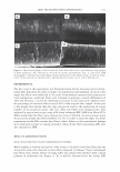
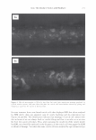
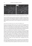
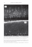
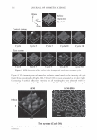
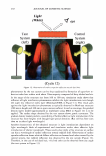
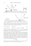
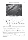
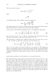
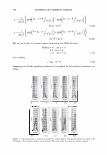
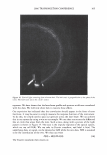
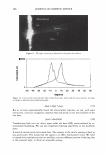
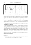
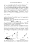
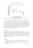
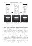
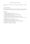
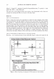
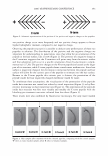
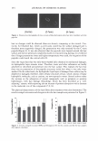
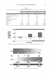
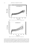
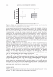
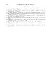
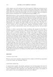
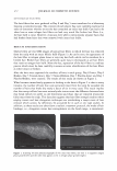
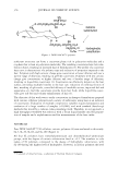
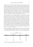
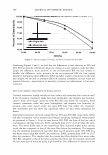
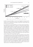
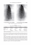
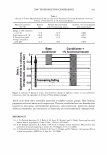
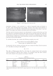
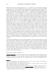
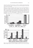
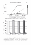
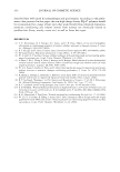
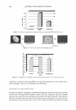
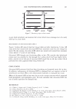
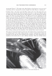
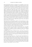
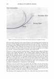
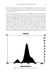
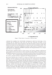
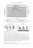
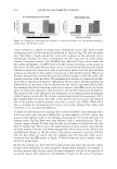
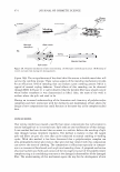
2006 TRI/PRINCETON CONFERENCE 297 Figure 2. A micrograph of a human hair. I '◄ ►' I Period, P I Figure 3. Coherent reinforcement of the waves reflected from each facet occurs when the phase delay is an integral number of wavelengths. We can now write the scalar field amplitude A, by integrating over a period (2). The contributions from all the other facets will yield the same result p p 1 f r exp(-jwt ) f Am = rA exp[j(cp(x) - nKx - wt)]dx = p A exp[j(cp(x) - nKx)]dx. 0 0 where j = (-1) 112 • As we are using complex notation the intensity in the mth order is the product of the electric field with its complex conjugate, denoted as Am * I - 2 IA *A m - r m m· (4) We see that we do not need to explicitly carry the time and frequency information, nor do we wish to track the overall factor due to surface reflectivity. We need only consider the spatial part
Purchased for the exclusive use of nofirst nolast (unknown)
From: SCC Media Library & Resource Center (library.scconline.org)