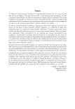
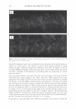
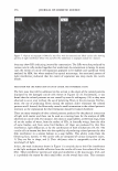
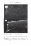
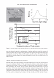
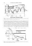
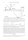
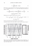
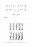
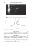
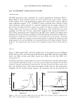
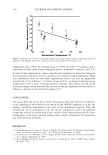
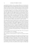
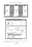
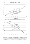
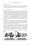
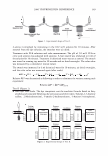
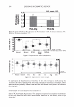
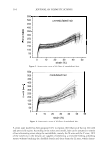
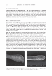
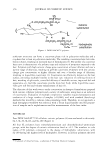
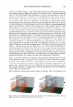
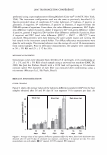
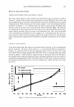
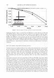
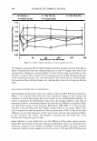
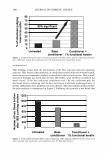
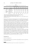
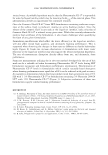
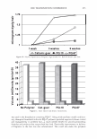
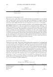
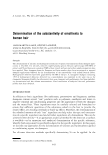
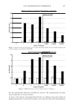
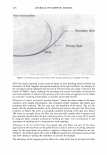
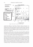
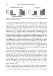
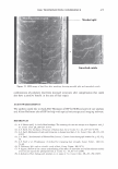
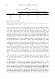
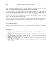
302 JOURNAL OF COSMETIC SCIENCE I = cr 0 { ERF('µ -al+&/ crv'z )-ERF('µ -aH/ crv'z)} for µ - al8 I = cr 0 { ERF(&-lµ -a'/ cry'z) +ERF('µ -al+&/ crv'z)} for +8 lµ-al We can write this in a more compact form using the SGN function. Let us define SGN(x) = -1 for x 0 = 0 for X = 0 = +1 for X 0 (12a) (126) (13) (14) Summing over all the significant orders (to /), weighted by their relative intensities, we obtain 0 0.1 .2 0.5 0.6 0.7 0.3 0.8 0.4 ·• O • I 12 SNII(_.. .. 0.85 Figure 7. Intensity plotted as a function of angle for various depths. The grating period was taken to be 10 microns. The indicated depths are in microns. The areas under the curves are nearly constant.

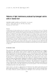
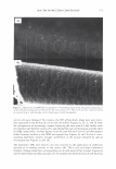
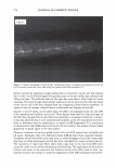
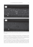
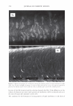
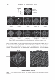
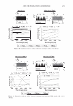
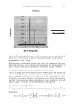
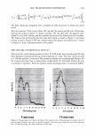
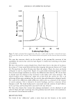
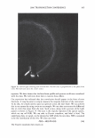
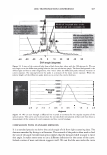
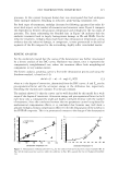
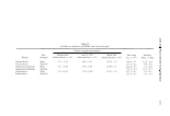
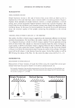
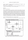
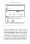
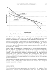
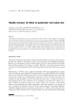
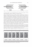
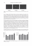
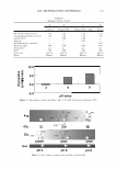
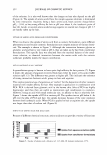
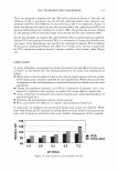
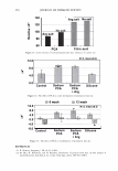
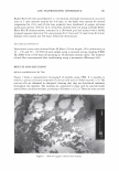
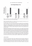
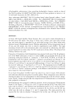
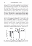
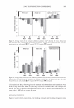
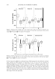
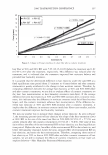
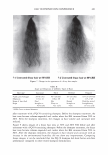
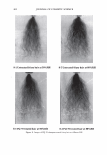
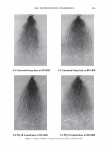
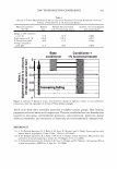
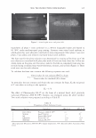
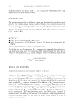
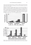
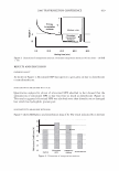
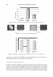
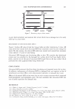
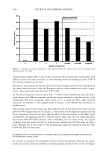
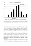
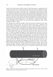
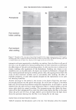
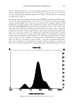
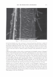
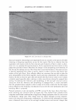
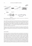
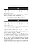
2006 TRI/PRINCETON CONFERENCE 303 I = � sin2 a { ERF('i +28/ vi)-SGN(Y.)ERF('JGN('J/ vi)}· coca! .L.J ( . ) 2 CJ 2 '=z CJ 2 i=O O'. - t1T (15) We have implicitly integrated over a number of delta functions to obtain the above result. We plot equation 15 for typical values. We can take the grating period to be 10 microns, spacing the orders at about 3.6 degree intervals. We can then take the aperture half- width, 8, to be 0.03 radians, and the standard deviation of the Gaussian as 0.01 radians. The shape of the central peak depends upon both depth, as shown in Figure 7, and upon period, as seen in Figure 8. We can compare these plots against actual data that is traced in Figure 9, from a photogoniometer (old model). PRELIMINARY EXPERIMENTAL RESULTS We have built a new photogoniometer with a 65 mW diode laser (wavelength 658 nm) from Newport Corporation having a beam diameter of 1 mm. The laser can be focused to a 100 micron lens, if required. The power has allowed us to photograph (Figure 10) the conical scattering that is characteristic of hair fibers (4). The light within the ring is considered "specular", while the light at smaller and larger radii is considered diffuse. a.. E C -4 -2 a 2 4 a a 10 12 14 1a Shift (degrees) 9 microns -4 -2 o 2 4 a a 10 12 14 1e Shift (degrees) 10 microns Figure 8. The grating period impacts the shape of the intensity curve. Both gratings were taken to be 0.15 microns deep. However, the curve on the left assumed a 9 micron period, while the one on the right was for a 10 micron grating. All other conditions are the same.
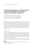
Purchased for the exclusive use of nofirst nolast (unknown)
From: SCC Media Library & Resource Center (library.scconline.org)