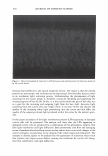
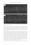
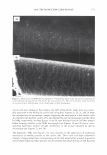
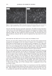
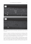
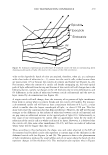
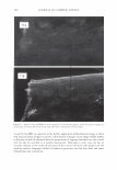
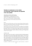
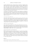
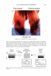
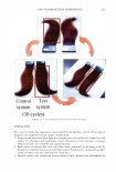
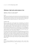
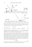
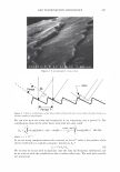
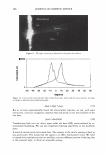
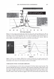
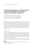
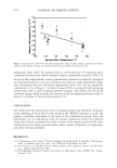
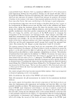
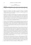
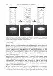
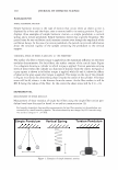
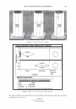
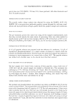
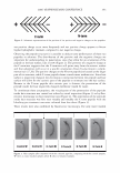
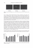
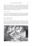
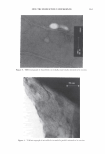
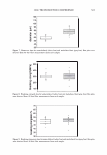
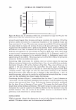
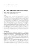
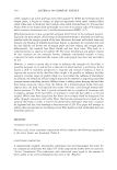
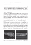
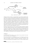
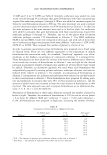
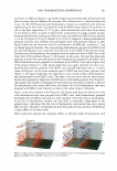
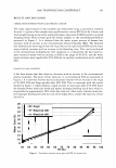
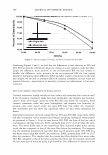
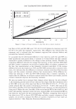
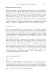
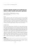
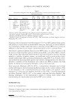
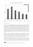
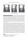
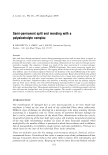
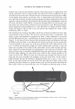
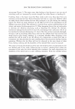
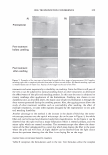
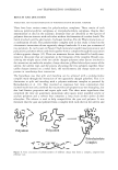
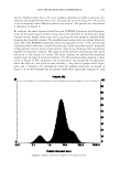
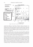
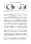
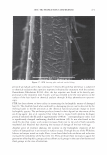
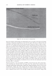
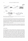
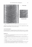
J. Cosmet. Sci., 58, 295-308 Guly/August 2007) Diffraction of light by the cuticle structure of hair HERSCHEL C. BURSTYN and Y ASH K. KAMA TH, TRI/Princeton, 601 Prospect Ave., Princeton, NJ 08542. Synopsis Under a microscope, hair looks like a surface relief grating with an irregular sawtooth profile. Using scalar diffraction theory, we model what has been, until now, assumed to be a specular peak in the light scattering data. Diffraction efficiencies are calculated as a function of cuticle thickness. Convolution with apertures and Gaussian processes yields a picture that is consistent with the observed position and structure of the "specular" peak. When the cuticle thickness fails to satisfy the blaze condition, the scattered light is distributed amongst multiple diffraction orders giving rise to a complex central structure. INTRODUCTION Reflection of light occurs at points where there are discontinuities in the index of refraction. Typically these occur at interfaces with air. In hair this region occurs at the surface of the cuticle (small shingles that cover the hair shaft). This observation has been used to quantify hair luster. The models that have been used to interpret the data have been based upon geometrical optics. The rake angle of the cuticle relative to the longitudinal axis of the hair, -y, is measured by determining the "scattering angle" twice: first with the hair oriented from root to tip, and then from tip to root. The difference in these two directions is equal to four times the rake angle (as the deviation from the "expected direction" in each case is twice the rake angle). The geometrical optic inter- pretation of the rake angle is demonstrated in Figure 1. If one models the hair as a grating, the angles into which diffraction occurs are fixed by the periodicity. This model is motivated by micrographs of which Figure 2 is one example. However, the energy that appears in any given order will depend upon the grating depth. It is this shift in the energy distribution that yields a perceived shift in the angle of "specular" reflection. It also explains why the specular assumption yields a rake angle estimator that can be a few tenths of a degree in error. This can be shown using scalar diffraction theory. The redistribution of energy amongst the diffraction orders, also expresses itself as changes in the shape of the peak, something that has been ignored to date. THEORY We start with the development of the grating equation (1). Only at specific angles does the light reflected off the facet surfaces add coherently. This can be seen in the Figure 3. 295

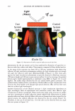
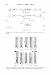
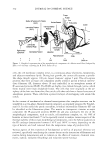
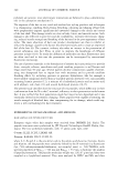
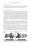
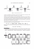
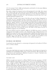
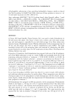
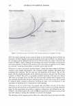
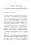
296 JOURNAL OF COSMETIC SCIENCE \ \ Tip to Root \ \ I I I I Figure 1. A depiction of the surface of a hair, showing: the rake angle"{. The normal the cuticle is shown as a dashed line. The "expected reflection direction" is shown in blue. The outgoing direction of the outgoing beam is deviated by 2"{ in each case, as shown above. The effective period is the revealed face of the cuticle, and the depth of the grating is simply the thickness of a cuticle. The condition is that: More generally we have, P sin 0 = mA.. ml\ mK Li�= Sin0incidenc - Sin0diffracted = p = T· (la) (lb) The integer, m, specifies the diffraction order (0, ±1, ±2, ±3, etc.). The wavelength of the light is A., while k = 2Tr!A. is the associated wavevector. The grating period is denoted with P, while K = 2TrlP is defined as the grating wavevector. We can find an expression for the optical electrical field by noting how the grating affects the incoming wave. First there is a reflection coefficient, r. This multiples the overall amplitude. There is also a reversal in direction in the y direction. Conservation of energy requires that the magnitude of the wavevector be conserved, but the grating equation indicates a change in the component in the x-direction, of mK. The product, mKx, represents the change in phase, relative to the plane that is the grating, as one scans horizontally. The phase shift due to the surface relief is simply twice the change in depth of the grating profile (round-trip distance). We use D, to represent the maxi- mum relief. The one way phase change is then a= 2TrD / 'A · (2) The depth is thus measured in units of wavelength, where a one wave shift represents a change in phase of 2Tr. The maximum round-trip phase change is 2a.
Purchased for the exclusive use of nofirst nolast (unknown)
From: SCC Media Library & Resource Center (library.scconline.org)