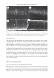
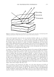
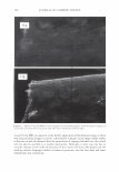
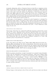
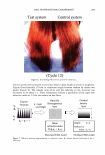
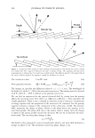
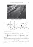
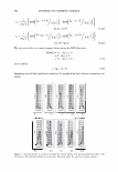
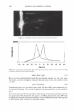
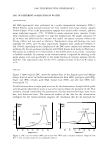
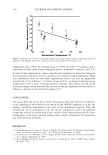
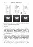
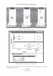
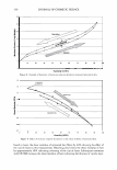
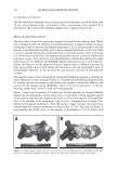
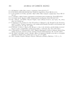
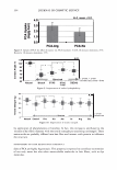
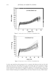
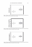
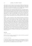
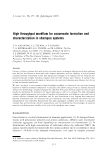
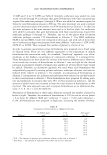
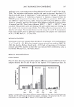
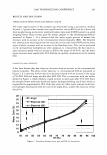
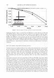
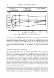
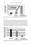
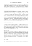
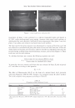
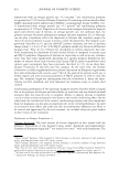
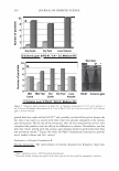
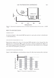
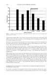
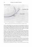
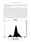
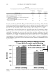
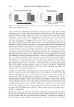
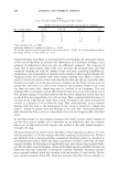
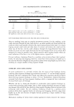
2006 TRI/PRINCETON CONFERENCE 299 Intensity f -••- lntens ity I Shift (degrees) Figure 5. At specific depths energy is distributed amongst a number of orders, at other depths the grating is blazed for the wavelength of interest and all the energy is contained in a single order. The position of the orders is set by the mean periodicity of the grating. Ablation will increase facet spacing variability. EXPERIMENT AL SIMULATION Real experiments use lasers with Gaussian beam shapes the illumination optics has a finite beam divergence, and the detector has finite aperture size. This means that the signal is really a convolution of the diffraction pattern with real system artifacts. THE DIFFRACTED ORDERS ARE SPATIALLY INCOHERENT WITH EACH OTHER The first issue that needs to be addressed is mixing between orders. We note that the orders exit at different angles from the sample (nominally with 4 degree separations). This means that the outgoing plane waves, that are the orders, will be tilted with respect to each other. Many fringes will appear across the photosensitive surface. This means that the orders will not be spatially coherent at the detector, and any cross beating terms will explicitly cancel. We can add the intensities of the orders incoherently. THE LASER HAS A GAUSSIAN BEAM SHAPE The laser beam profile is Gaussian, and as such its properties are well known. We can assume that the minimum waist is at the hair (z = 0) and that the electric field propagates as E(r,z) = E0 11 �:) exp [ - 11 � :) 2] exp [ - j( kz - arctan ( :J + 2�:)) ]- (S a )

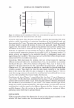
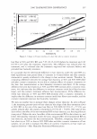
300 JOURNAL OF COSMETIC SCIENCE The beam's radius Tl, goes as where ( ( z ) 2 )1/ 2 Tj(z) = 1lo 1 + ZR is the Rayleigh range. The wavefront curvature propagates as (9) The Rayleigh range is that distance over which the beam does not significantly diverge. Notice that the beam is a plane wave both at focus and at infinity. If our detector is well within the Raleigh range we can simplify the expression to (86) For a beam with a waist of 1 mm = 1000 µm, the Rayleigh range of the order of 5 meters (@0.63 µm). If focused to 100 microns this reduces to 4.9 cm. This distribution is centered upon a diffraction order which is located at 0 0 . As such, r = z(0 - 0 0 ). We can define Tj 0 /z as D and rewrite the expression as [ (0 - 0o)2 ] [ ( ( z ) ) ] E(r,z) = Eo exp - n2 exp - j kz - ZR (8c) Thus we can also interpret the spatial distribution as an angular one. The propagating phase part is nominally a plane wave that will have almost no effect on the final observed intensity. The observed intensity in the plane of the detector, for a single order, will be a Gaussian distributed in angle about a direction that is specified by the grating equation. GRATING PERIOD VARIABILITY CAN BE MODELED AS A GAUSSIAN PHASE SCREEN We modeled the hair as a phase grating of specific period. The cuticles, as they wear, will thin and fracture. We have shown how the depth can be accounted for in a scalar diffraction theory. We need to somehow account for the increased variability in the pitch. There is however a local modulation of period. A random modulation can be accounted for by introducing a Gaussian phase screen as a transmission mask. Because the screen acts multiplicatively in real space, it appears as a convolution in the transform space (3 ). In other words the Gaussian profile that is the laser's beam cross-section is convoluted with phase screen's Gaussian in angle space, resulting in what may be referred to as an excess spreading about the mean (angular) position. This is explicitly expressed in the following way.
Purchased for the exclusive use of nofirst nolast (unknown)
From: SCC Media Library & Resource Center (library.scconline.org)